|
To help you get answers quickly, we have compiled commonly asked questions and put them into an online knowledge base. You can also search our FAQ database.
- How can I troubleshoot my 2-1/16" Comp II Fuel Level Gauge?
Every Comp II LED fuel level gauge is checked multiple times during assembly and again before it ships. Because of the multiple checks we perform problems with the gauge are very rare. Issues with the Comp II fuel level gauge are typically caused by:
- Not having a good common ground for both gauge and sender, often caused by the fuel level sender not having a good ground.
- Not having a good signal to the gauge.
Make sure your sending unit has a good ground. Recheck your wiring for the fuel level gauge and make sure that the gauge and the sender have a common ground. If in doubt ground them at the same location.
Disconnect the fuel level signal wire and measure the ohms on the signal wire with an ohm meter (multi meter). If possible confirm the ohms signal near empty and near full.
If you do not get a good reading your sender may be bad and require replacing.
Option 1: Check by Grounding the Signal
Hook up power and ground to the gauge but do not connect anything to the signal connector (S). On a 0-90 ohm fuel level gauge with no signal and power on the pointer should go all the way to the left. Now add a ground connection to the S terminal (use a jumper wire between G and S terminals) while keeping the power (I) and ground (G) connections in place. With a grounded signal connection (0 ohms input) the pointer on a 0-90 ohm gauge should move up towards the E marker.
Option 2: Check with a Resister
Another way to verify the gauge is working correctly is to "fake" a signal by putting a resistor across the S (signal) and G (ground) terminals. A 47 ohm resistor is ideal. On a 0-90 ohm fuel level gauge a 47 ohm "signal" will move the pointer to approx 1/2. The pointer will move to a different position for other ranges of fuel level gauges (i.e. 73-10 ohm, 20-150 ohm).
If you have a resister of a different value it will move the pointer to the corresponding dial position for your specific fuel level gauge. For example, if you use a 100 ohm resister on a 0-90 ohm fuel level gauge the pointer will go to Full +.
Option 3: Check with Another Known Good Signal
If you don't have access to a resister you can use the signal from your oil pressure gauge to test the fuel level gauge. Connect the power, ground and signal from the oil pressure gauge and connect them to the fuel level gauge.
If you have a 0-90 ohm fuel level gauge the pointer should move to a similar position as the pointer did on the oil pressure gauge. If you have another range fuel level sender the pointer will move to a different location but should still move. If the fuel level gauge responds with the oil pressure connections you know the gauge is good.
View FAQ
- How can I troubleshoot my 2-1/16" Comp II LED Gauge?
Each Comp II LED 2-1/16" gauge is checked multiple times during production and again before each gauge ships. Most problems are caused by improper installation. You can confirm your gauge is OK by performing the following quick checks with a standard 9V battery (make sure battery is fully charged).
Confirm Gauge Powers Up Correctly
- Volts: Place the + battery terminal on the gauge "I" terminal and the - battery terminal on the gauge "G" terminal. The gauge will move to 8-9V (depending on your battery voltage.
- Pressure & Regular Fuel Level Ranges (0-90, 0-30, and 73-10 Ohm): Place the + battery terminal on the gauge "I" terminal and the - battery terminal on the gauge "S" terminal. The gauge will move to left side of scale.
- Temp & Inverse Fuel Level Ranges (240-33, 73-10 Ohm): Place the + battery terminal on the gauge "I" terminal and the - battery terminal on the gauge "S" terminal. The gauge will move to right side of scale.
Confirm Gauge With Simulated Signal
To verify operation of the gauge with a simulated signal (not necessary for VOLTS gauge) you will need a 9V battery, some 18-22 gauge wire and a 100 ohm resistor (other ohm value is OK also but gauge output shown below will vary). Connection power and signal as follows:
- 9V+ to gauge "I"
- 9V- to gauge "G"
- One end of resistor connected to 9V-, the other end connected to gauge "S"
For a 100 ohm resister, the gauge should go to the following approximate positions:
- Pressure: 80+ PSI
- Temp: 180-200F
- Fuel Level (0-90, 0-30 Ohm): Full+
- Fuel Level (20-150 Ohm): 1/2 - 3/4 FULL
- Fuel Level (73-10 Ohm): EMPTY
- Fuel Level (240-33 Ohm): 1/2 FULL
View FAQ
- How can I troubleshoot my electric oil pressure gauge?
Most issues are due to incorrect wiring or sender hookup. The most common wiring issue is not having a good common ground between the gauge and sender. A common indicator of not having good wiring on your sender is the pointer on the Comp II LED oil pressure gauge going all the way to the right (open circuit on signal wire).
Check the Gauge with 0 Ohm Signal (Ground)
Connect the signal from the gauge to the gauge ground wire. This puts a signal of 0 ohms to the gauge. A Comp II LED gauge with 9200 sender will go to 0 PSI. A current SCX gauge with 9205 sender will go to 100 PSI.
Confirm the Gauge is OK by Using a Known Good Signal
Use a 47 ohm or 100 ohm resistor to verify the gauge with a known good signal other than 0 ohm (ground):
- Install one end of the resistor to the gauge signal input and the other end to the gauge ground.
With power to the gauge and a resistor across the signal input and ground you will see the pointer move to to the corresponding dial position.
- For gauges with 9200 sender: 47 ohms is approx 40 PSI, 100 ohms is approx 80 PSI.
- For gauges with 9205 sender: 47 ohms is approx 90 PSI, 100 ohms is approx 70 PSI.
If you do not have access to a resistor but do have another working fuel level or temp gauge you can use the power, ground and signal connections from the known good gauge on the oil pressure gauge to verify that the oil pressure gauge is OK. Note, the pointer will move according to the ohm output from the sender you are using to test the gauge.
Confirm the Type of Sending Unit You Have
There are three types of oil pressure sending units. Confirm which sender you have and make sure that it is putting out a good signal and that it has a common ground with the gauge. We recommend grounding the gauge and sender together to eliminate any potential issues with not having a good common ground.
- Type 2 is the most common sender (Our part 9200). It has a yellow label stating "WK = Ground". This type of sender is supplied with Comp II gauges and SCX gauges shipped after May 1, 2022.
- Type 3 (our part 9205) is silver in color and has a white label stating "240-33 OHM (0-100 PSI)". This sender was supplied with most SCX gauges shipped 2015 through May 2021.
- Type 1 has no label. This sender was supplied with most SCX gauges shipped before 2015. This sender does not have a ground terminal. The sender is grounded through the body of the sender.
Verify Wiring and Common Ground
Verify your wiring is good and that the gauge and sender both have a good common ground. We recommend grounding the gauge and sender together to eliminate any potential issues with not having a good common ground.
If you have a Type 1 sender (no label) make sure you have not connected anything to the WK terminal. Verify the sending unit has a good ground connection on the body of the sender. If in doubt, install a metal clamp around the sender body and run a wire from the clamp to a good ground location on the vehicle chassis.
Verify Ohm Signal from Sending Unit
Turn your vehicle on and let it idle. Disconnect the gauge signal wire from the sender and check the ohms output with a multi-meter as follows:
- For 9200 sender, the G terminal is the signal and the WK terminal is the ground.
- For 9205 sender, - terminal is the ground and S terminal is the signal.
- For old Type 1 sender, the G terminal is the signal and the body of the sender is ground.
Check the SCX or Comp II pressure/ohm data (found here) and confirm that the sender ohm output is reading as expected.
Verify Ohm Signal at the Gauge
Reconnect the gauge signal wire to your sender, disconnect the signal wire from the gauge and check the ohms between the signal wire and gauge ground wire (signal wire needs to be disconnected from the gauge). The ohm reading should be the same as you measured at the sender. If it is not, then you will need to check your wiring (verify common ground etc.).
View FAQ
- How can I troubleshoot my electric temperature gauge?
Verify Wiring and Common Ground
Not having a good ground between the gauge and sender is the most common issue. Verify your wiring is good and that the gauge and sender both have a good common ground (ground both to the same place on the chassis). The 9204 temperature sending unit does not have a ground wire connection, it grounds through the body of the sending unit. It may be necessary to run a wire from the body of the 9204 sending unit to the gauge ground location if your sender does not have a good common ground with the gauge.
Verify Ohm Signal from Sending Unit
Turn your vehicle on and let it warm up. Disconnect the gauge signal wire from the sender and check the ohms output between the sender and common ground/chassis with a multimeter. Compare the ohms output with the expected ohm output at warm temperature. Temp/Ohm data for the SCX and Comp II temperature senders can be found on the respective product pages:
If the sender is not reading as expected contact us for a replacement.
Verify Ohm Signal at the Gauge
Reconnect the gauge signal wire to your sender, disconnect the signal wire from the gauge and check the ohms between the signal wire and gauge ground wire (signal wire needs to be disconnected from the gauge). The ohm reading should be the same as you measured at the sender. If it is not, then you will need to check your wiring (use smaller gauge wire, verify common ground etc.).
Verify the Gauge
Check the SCX or Comp II temp/ohm data on the respective pages above and confirm that the gauge is reading at the expected temperature for the ohms reading at the gauge. Example: at 200 ohms, the SCX temp gauge should read approx 180F. If the gauge is not reading as expected contact us to return your gauge for checking/replacement.
View FAQ
- How can I troubleshoot my fuel level gauge?
Most issues are due to incorrect wiring or having a mismatched fuel level gauge and sender (i.e. using a 0-90 ohm gauge with a 73-10 ohm sender). The most common wiring issue is not having a good common ground between the gauge and sender.
Verify Wiring and Common Ground
Verify your wiring is good and that the gauge and sender both have a good common ground. We recommend grounding the gauge and sender together to eliminate any potential issues with not having a good common ground.
Verify Ohm Signal from Sending Unit
Disconnect the signal wire connection from the sending unit and verify the ohm output of the sender at various positions with an ohm meter (i.e. 0 ohm @ empty, 50 ohm @ half, 90 ohm @ full). Verify that you have the correct range fuel level gauge for your sending unit.
Verify Your Fuel Level Gauge Range Matches Your Sending Unit
Comp II LED fuel level gauges have a sticker on the back of the case indicating the range of the fuel level gauge (i.e. 90 for 0-90 ohm, 73 for 73-10, 240 for 240-33). You can verify the fuel level range setting for a SCX gauge by following the calibration procedure in the instructions and noting the location of the pointer after entering calibration mode.
Confirm the Gauge is OK by Using a Known Good Signal
Disconnect the signal wire connection from the gauge and use a 47 ohm, 100 ohm resistor and a 0 ohm (signal connection grounded) to verify the gauge operation with a known good signal. Install one end of the resistor to the gauge signal connecton and the other end to the gauge ground connection. For a 0 ohm signal input, ground the signal connection.
- For a 0-90 fuel level gauges: 47 ohms is approx 1/2 of a tank, 100 ohms is Full +, 0 ohms (signal grounded) is Empty.
- For a 73-10 fuel level gauges: 47 ohms is approx 3/8 tank, 100 ohms is Empty -, 0 ohms (signal grounded) is Full +.
- For a 240-33 fuel level gauges: 47 ohms is almost Full, 100 ohms is approx 3/8 of a tank, 0 ohms (signal grounded) is Full +.
View FAQ
- How can I troubleshoot my speedo hall effect sender?
You can check the GM/Mopar (Item 9220) or FORD (Item 9222) hall effect senders as follows:
- Make sure the harness is secure and connected properly. Verify the harness is flush with the body of the sender and the side clips are fully engaged. Pull on the harness head to confirm it is installed properly.
- Connect 12V power (red) and ground (black) to the sender harness wires.
- Connect a volt meter* positive lead to the signal output wire from the sender (white). Connect the volt meter negative lead to the sender ground (black).
- Turn the sender key (the square part that turns) slowly by hand. If the sender is good you will see the VOLTS go from 0V to 12V and back to 0V. The voltage value will cycle from 0V to 12V sixteen times for a full rotation of the sender key (16 pulses per revolution).
*If you don't have a volt meter you can use a 12V bulb to indicate the 0V and 12V outputs. Make sure you hook the bulb up correctly before testing. The bulb will light up when the voltage output from the sender is 12V and will be off when the output from the sender is 0V.
View FAQ
- How can I troubleshoot my speedometer?
Problems with the speedometer are very rare. If you are having issues it is most likely that your signal or ground is bad.
Verify You Have A Good Common Ground
Make sure that your speedo sender and the speedometer have a good common ground. If in doubt, ground them together on a good ground location.
Verify You Have A Good Signal
You can verify your signal by monitoring the pulses that get counted during calibration:
- Enter calibration mode
- If you see pulses being counted on the ODO while not moving then you most likely have signal noise. This can be due to a bad sender or wiring.
- Start driving a measured mile at a steady speed and have someone monitor the pulses that are being counted on the ODO display.
- If your signal is good you will see pulses count incrementally (not erratic). The pulses will increment at a faster rate the faster you go, so if you drive a steady speed (i.e. 25mph) you should see the pulse count increment at a steady rate. If the pulses increment erratically then you do not have a good signal. Erratic pulse count while driving a steady speed during calibration indicates you most likely have a bad sending unit.
View FAQ
- How do I calibrate my electric speedometer?
Speedo Calibration
- With the ignition off, press and hold the CAL/TRIP button. Turn the ignition on, then release the CAL/TRIP button.
- The odometer/trip display will indicate CAL to verify that calibration mode has been accessed. The pointer will move to 50% scale.
- Drive the vehicle EXACTLY one (1) measured mile then stop.
- Press the CAL/TRIP button again to complete the calibration.
- If the number of pulses is between 4,000 to 200,000 the odometer/trip display will indicate the actual pulses counted by the speedometer for five (5) seconds. This indicates a successful calibration. The speedometer will return to normal operation automatically.
If the number of pulses is below 4,000 at the end of one mile, the odometer/trip display will show zeros for five (5) seconds after the button is pressed. The calibration will not be updated, and the original calibration will be maintained. If this occurs you most likely have a problem with your sender and/or wiring. Correct the problem and recalibrate the speedometer.
If the number of pulses is above 200,000 at the end of one mile, the odometer/trip display will show zeros for five (5) seconds after the button is pressed. The calibration will not be updated, and the original calibration will be maintained. Correct the problem and recalibrate the speedometer.
View FAQ
- What is the thread size on the temperature and pressure senders?
The temperature and pressure senders have a 1/8" npt connection (male).
LS1 Metric Connections
For LS1 applications you will most likely need a metric to 1/8" npt adapter. For example: a M12 1.5 male x 1/8" npt female adapter for the temp sender and a M16 1.5 male x 1/8" npt female for the oil pressure sender. These are not included but can be readily found on eBay and Amazon.
View FAQ
- What senders are included with the SCX and Comp II LED Gauge Sets?
2-1/16" Gauges
The oil pressure and water temp sending units are included. They have 1/8" NPT male connections. The volts gauge does not require a sender, you get the signal from the 12V ignition circuit.
For some applications you may need adapters to install the sending units.
For example, LS applications have metric connections so you may need a M12 1.5 male x 1/8" npt female adapter for the temp sender and a M16 1.5 male x 1/8" npt female for the oil pressure sender. Oil pressure sandwich adapaters and water temperature sender adapters can also be used for installing the oil pressure and water temperature senders. These adapters come with 1/8" NPT female ports. Adapters are not included but can be readily found online.
A fuel level sender is not included. The SCX and Comp II LED fuel level gauges can be programmed to work with the five most common fuel level sender ranges (0-90, 73-10, 240-33, 0-30 and 20-150 ohm). Check your current fuel level sender output (Empty - Full) before ordering. If necessary we can supply a fuel level module that will allow you to use a mismatched sender and gauge.
Tachometer
If you have a standard ignition coil, ignition box with tachometer signal output (i.e. MSD 6AL) or ECU 12V tachometer signal you do not need anything additional to hook up your tachometer. See the How do I hook up my tachometer? FAQ for more info.
Speedo
If you have a hall effect sender, GPS sender or magnetic speed sensor (i.e. vehicle speed sensor) already available the speedometer should work without any additional sending units. See the What will I need to make the electric speedometer work? FAQ.
View FAQ
- What will I need to make the electric speedometer work?
If you have a hall effect sender, GPS sender or magnetic speed sensor (i.e. vehicle speed sensor) already available the speedometer should work without any additional sending units.
Any speed sender or electronic module that meets the following conditions can be used with our speedo:
- Pulse range generated proportional to the vehicle speed
- Signal with minimum 3V peak to peak signal - typical for 3-wire hall effect and 2 wire vehicle speed sensor outputs
- 4000-200,000 pulses per mile (16,000 is typical).
Important
- Do not split the speedo signal.
- Make sure the signal source and the speedo have a common ground.
- Make sure the signal wire is routed away from sources of high voltage (i.e. ignition systems) or other sources of signal interference.
If you currently have a mechanical speedometer (cable driven) you will need a hall effect sender. The hall effect sender connects where the cable currently comes off. The signal from the hall effect sender provides the signal for the electric speedo. We sell hall effect senders for both GM/Mopar and FORD applications.
If none of the above options will work for your application the best option is to purchase a GPS speedo sender. Google "GPS Speedometer Sender" to find places to purchase.
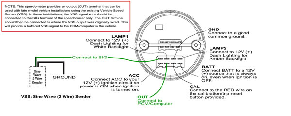
Late Model Vehicles with PCM/Computer
This speedometer provides an output (OUT) terminal that can be used with late model vehicle installations using the existing Vehicle Speed Sensor (VSS). In these installations, the VSS signal wire should be connected to the SIG terminal of the speedometer only. The OUT terminal should then be connected to where the VSS output was originally wired. This will provide a buffered VSS signal to the PCM/computer in the vehicle.
View FAQ
- Why won't the lighting work on my 3-3/8" speedo and tachometer?
The Comp II LED and SCX 3-3/8" speedo and tach feature integrated LED lighting. For the backlight to turn on you must also have 12V power to the gauges turned on (ACC).
When checking the lighting make sure the following are connected:
- 12V ACC
- Ground
- 12V to light input
View FAQ
- How Can I Reduce the Responsiveness of My Fuel Level Gauge?
Installing a capacitor between your signal input and ground connections will reduce the responsiveness of your fuel level gauge.
A 5.5V 1.5F capacitor provides good dampening. Use a higher value capacitor for more dampening. i.e. A 5.5V 4F capacitor slows the pointer down so it takes approx 45 seconds to go from 3/4 to 1/2 and back to 3/4.
Install the capacitor as shown in the diagram below. One side of the capacitor should be connected to the signal (S) terminal. The other side of the capacitor should be connected to the ground (G) terminal.
Note: It is important you use the correct capacitance (F) and Voltage rating.
The SCX performance gauges are very responsive which can lead to a lot of pointer fluctuation on your fuel level gauge if your fuel tank has a lot of sloshing.
You can dampen the pointer response by adding a capacitor between your signal input and ground wires as shown in the diagram below. A 1.5F 5.5V capacitor gives good dampening. For increased dampening use a capacitor with higher Farad (F) value
Note: It is important you use the correct capacitance (F) and Voltage rating.
View FAQ
- How do I calibrate my SCX gauge?
To change the calibration setting:
- To access calibration mode, turn the power to the gauge on with the
CAL wire grounded. The CAL wire is the GREEN wire on Pin 3 of
Connector 2 (see Fig 1 on SCX Instructions).
- The pointer will stop at 50% scale to indicate you have
successfully accessed calibration mode.
- Once the pointer stops at 50% scale remove the CAL wire from
the ground source. The pointer will move to indicate the current
calibration setting per "Calibration Settings" below.
- To change the calibration setting, momentarily ground the CAL wire.
Each time you momentarily ground the CAL wire, the calibration
setting will change.
- When the desired calibration setting is obtained, leave
the CAL wire ungrounded for 5 seconds. The gauge will save the
new calibration setting, exit calibration mode and return to normal
operating mode.
Calibration Settings
- Vac/Boost with transducer (0.5-4.5V Output): 20% scale (12" Vac)
- Volts, 8-18V: 0% scale (8V)
- Oil Pressure with 9200 sender: 100% scale (100 PSI)
- Water Temperature 100-260F with 9201 sender: 88% scale (240F)
View FAQ
- How do I hook up my tachometer?
Standard Ignition Coil
If you have a standard ignition coil you can use the negative terminal of the coil for the signal source. Use the SIG 2 (In-Dash Tach) or green wire (Pedestal Mount Tach) input (see "Signal Hookup" in the instructions). If you have a high output capacitive energy discharge type coil it is recommended that you install a tachometer filter to prevent damage to the tachometer.
Ignition Box
If you have an ignition box (i.e. MSD 6AL) you can use the "Tach Output" from the ignition box. Use the SIG 1 (In-Dash Tach) or purple wire (Pedestal Mount Tach) input (see "Signal Hookup" in the instructions).
12V ECU Tachometer Signal
If you have a modern ignition system and your ECU (computer) has a dedicated 12V tachometer signal output you can use this to drive the tachometer. Use the SIG 1 (In-Dash Tach) or purple wire (Pedestal Mount Tach) input (see "Signal Hookup" in the instructions).
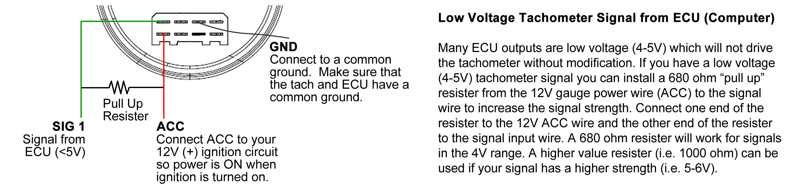
5V ECU Tachometer Signal
Many ECU outputs are low voltage (4-5V) which will not drive the tachometer without modification. If you have a low voltage (4-5V) tachometer signal you can install a 680 ohm "pull up" resister from the 12V gauge power wire (ACC) to the signal wire to increase the signal strength. Connect one end of the resister to the 12V ACC wire and the other end of the resister to the signal input wire. A 680 ohm resister will work for signals in the 4V range. A higher value resister (i.e. 1000 ohm) can be used if your signal has a higher strength (i.e. 5-6V). NOTE: Make sure your tachometer has a common ground with the signal source (ECU).
HEI
If you have an HEI distributor with a "Tach Output" you can use the "Tach Output" from the distributor. Due to the high voltage of the signal from the HEI you should use a tachometer filter to prevent damage to the tachometer.
Coil Pack or Individual Coils (Distributorless Ignitions)
If you have a modern vehicle with "coil pack" or "individual ignition coils" distributorless igntion you will need a tach driver like the MSD 8913 to drive the tachometer. Connect the signal from the tach driver to SIG 1 (In-Dash Tach) or purple wire (Pedestal Mount Tach) input.
Troubleshooting
If your tachometer has no signal or an erratic signal (pointer jumping all over) you first need to verify that you have correct power, ground and signal connections.
- Verify the gauge has 12V power. The gauge should perform a self calibration check when turned on (pointer moves to full scale, then back to zero).
- Verify you have a good common ground. A bad ground connection is often the cause of many gauge issues. Make sure the gauge ground connection is connected directly to a good ground on the vehicle chassis. We recommend using the same location as the battery negative terminal ground.
- Verify you are using a proper signal source. The most common locations for a tach signal are the negative terminal of the ignition coil or tachometer output terminal (HEI, Ignition Control Boxes or ECU).
No Pointer Movement
- Verify 12V ACC, signal and ground connections (see above).
- Verify you have a good signal that is at least 8V peak to peak in amplitude (requires an oscilloscope). Some ECU signals are not strong enough to drive the tachometer.
- Try switching the signal input. Marshall tachometers come with 2 signal input options.
Erratic Pointer Movement
- Verify correct signal and ground connections (see above).
- Verify your signal wire is not routed close to any high voltage sources (i.e. spark plug wires, distributor). The signal wire can pick up electrical interference (signal noise) if routed close to a high voltage source.
- Try switching the signal input. Marshall tachometers come with 2 signal input options, each input utilizes a different signal filter.
- Install a tachometer signal filter.
- Add a 10K Ohm resistor inline with the signal. Adding a resistor will increase the level of signal filtering. Try this on both signal inputs. Use a higher ohm resistor for more filtering, a lower value ohm resistor for less filtering. /ul>
View FAQ
- How do I stop my SCX gauge lighting from blinking?
Problem: SCX stepper motor gauge backlight blinks periodically.
Cause: Vehicle's computer sends diagnostic pulses through its lighting circuit. The diagnostic pulses interrupt the 12V supply to the gauge LED light circuit causing the gauges to blink ON/OFF periodically.
Fix: Install a 12V relay between the light circuit and the gauge lighting wire. This will isolate the diagnostic pulses and provide a steady uninterupted 12V power to the gauge lighting circuit.
View FAQ
- My Comp II LED Gauge Light Doesn't Work, What's Wrong?
Each Comp II (C2) snap-in bulb and socket is checked for correct operation before it is packaged so the problem is most likely incorrect wiring, loose bulb, or the bulb is installed backwards (applies to LED bulbs).
Wiring
Make sure the white wire lead is connected to a 12VDC+ supply (verify voltage with a multimeter). The black wire lead should be connected to Ground.
Verify the Bulb Clips Are Properly Aligned
There is a brass clip on the end of each wire that attaches to the bulb. Verify that the clips are positioned correctly inside the socket. The open part of each clip should point towards the center of the socket. The sides of each clip should be spaced such that the bulb base can be inserted and make good contact with the clip.
Adjust the Bulb Clips
If necessary you can remove the two wires from the socket (pull wire and clip back through the socket) to adjust the clips as necessary. Reinstall the wires back into the socket from the front and verify the clips are oriented such that the clip opening is facing the center of the socket and that the clips have enough space to allow bulb insertion.
Reinstall the bulb. When reinstalling the bulb hold the two wires firmly at the base of the socket to ensure that the bulb makes good contact with the clips.
Verify Bulb Polarity (LED Bulbs)
The LED bulbs are polarity sensitive. If the LED bulb is installed backwards it will not work. If your bulb does not light, remove the bulb, rotate 180 degrees and reinstall the bulb.
View FAQ
- My mechanical boost gauge buzzes, how can I fix it?
This is a very common problem with mechanical boost gauges.
Causes
At certain pressures the fast moving air is at the resonance frequency of the gauge which causes the gauge to buzz. The location of the PVC supply line is also a major cause (see below).
Solution
All that is typically needed to eliminate the noise is a restrictor to dampen the air movement in the hose to the gauge.
Our mechanical boost gauge includes a restrictor on the tee that helps prevent this. Other companies call it an "anti-buzz" or "no-buzz" fitting.
Please see other suggested solutions below:
- put a wad of cotton from a q-tip or cotton ball where the hose goes into the gauge
- install a small fuel filter (i.e. for a lawn mower) inline
Some additional install tips:
- use the included tee fitting with restrictor and/or additional vacuum restrictors in the tubing to the gauge
- make sure your tubing is fastened at various points (so it is not loose)
- it is better to locate the PVC tubing pressure source further from the turbo (i.e. in the manifold just before the engine).
Google boost gauge buzzing for more information on this subject.
View FAQ
- My speedometer pointer is erratic, how can I fix it?
The most common causes of erratic pointer movement are:
- Bad ground. Make sure the ground connection on the gauge is connected to the same spot as the car battery ground to ensure you have a good ground. Do the same for the sensor (the gauge and the sensor need to have a good common ground).
- Externail noise. Noise introduced from routing the signal wire close to a high voltage electric source (i.e. spark plug wire, ignition). Make sure your signal wire isn't picking up any noise.
- Bad or incorrectly installed sender. Ensure your sender is operating correctly and it producing a good signal.
If you are still seeing some noise after checking the above items, try adding a 0.05uF (micro Farad) or 0.1uF capacitor across the input to ground. If signal noise is the issue, this will help filter out any signal noise and smooth pointer response.
View FAQ
- What are the dimensions of the gauges?
To verify if the gauges will fit your existing dash panel check the hole sizes and spacing against the gauge case od and bezel OD:
The 5 inch in-dash gauge case OD is approx 4.57" (4-9/16", 116mm) and the bezel OD is approx 5.0" (125mm). You want your hole size to be around 4.75" but anything between 4.6" and 4.9" is OK. Case depth is approx 1.75" not including the uclamp studs.
The 2-1/16" gauges have a case OD of approx 2-1/16" (52mm). The bezel OD is 2.25" (57mm). Case depth is approx 1.25" not including the uclamp studs. The uclamp studs are 0.75" long.
The 3-3/8" gauges have a case OD of approx 3-3/8" (86mm). The bezel OD is approx 3.75" (95mm). Case depth is approx 1.75" not including the uclamp studs. The uclamp studs are 1" long.
If you do not have an existing panel with these size holes you may need to modify your existing panel or purchase an aftermarket dash panel for your vehicle. We recommend checking with Classic Dash to see if they make a dash panel for your application. To find other manufacturers of after market dash panels do a Google search for "dash panel" plus the make and model of your vehicle, i.e. "dash panel for 1979 Camaro".
View FAQ
- What is the BATT (Always On) Connection For?
The BATT (Always On) connection is required for the SCX based stepper motor gauge pointer to return to 0 when the ignition is turned off.
If you do not connect the BATT gauge connection to the battery + (always on) connect it to your 12V ignition source so the 12V BATT connection has full 12V power when the ignition is ON.
Without 12V power to the BATT connection the stepper motor gauge pointer will stay at its last reading (i.e. 30 PSI, 200F, 800 RPM etc) when the ignition is turned off. This does not affect the gauge (other than the pointer not returning to 0). When the ignition is turned back on, the gauge will perform its self calibration cycle and operate normally.
View FAQ
- What is the warranty on the gauges?
If the gauge was purchased within the previous 12 months from an authorized distributor you are covered under warranty. Contact us with your item and proof of purchase for an RMA number and return instructions before returning your item. Sending units and accessories are not covered under warranty.
Return Address
Marshall Instruments
RMA: *supplied RMA number*
2930 East La Cresta Ave
Anaheim, CA 92806
Return Instructions
- Return only the gauge. Keep any accessories that originally came with the item (u-clamp, light, sending unit etc).
- Make sure you include your full contact information inside the package (name, email, phone and address) so we can contact you with questions.
- Make sure you ship via a trackable method (USPS First Class is inexpensive and offers tracking). We are not responsible for lost items.
- Return shipping charges may be applicable (see fees below).
- For returns/repairs covered under warranty include a copy of your proof of purchase. It needs to clearly show the item, date purchased, your name and shipping address.
Fees
Items less than 1 year old with proof of purchase:
- Return shipping to a USA address via standard USPS service: No charge
- Shipping to a non USA address or oversize package: Charge based on actual return shipping cost
Items over 1 year old or no proof of purchase:
- Comp II LED 2-1/16" Gauges: $30.00ea
- SCX 2-1/16" Gauges: $50.00ea
- 3-3/8" Speedometers and Tachometers: $60.00ea
- 5" Speedometers and Tachometers: $75.00ea
Prices above include standard first class USPS return shipping to a US address. An additional fee applies for oversized items, expedited shipping or shipping outside the US.
View FAQ
- How can I dim my SCX gauges?
The SCX gauges feature integrated LED lighting and will not dim as desired when connected to a standard OEM dash dimmer.
To dim your SCX gauges we recommend installing one of our compact LED dimmer modules.
Alternate Option 1: Dimming Gauges With A Resistor
You can also dim the gauges by installing a resistor inline with the 12V ACC supply to each SCX gauge (not inline with the light connection). Installing the resistor lowers the voltage supply to the gauge which reduces the brightness of the lighting. A 0.5W 100 ohm resistor for each gauge works well however you can vary the resistance to your desired brightness.
If you dim the lighting using a resistor:
- Make sure the 12V+ "Always On" connection to the SCX gauge is connected (see instructions). This connection must get a steady 12V supply.
- Make sure you connect the resistor inline with the 12V ACC power to the gauge, NOT the lighting.
- If your resistor value is too high, the gauge may not get enough power to operate correctly. If this happens, lower the ohm value of the resistor.
Alternate Option 2: Dimming Gauges With a Potentiometer
For adjustable levels of dimming, you can install a potentiometer to reduce the voltage supply to each gauge (which will dim the lighting). For 1-3 gauges we recommend a 5W 250 ohm potentiometer (Digikey Part CT3018-ND). For 4+ gauges we recommend a 5W 100 ohm potentiometer (Digikey Part 026T419S101A1A1-ND).
If you dim the lighting using a potentiometer:
- Make sure the 12V+ "Always On" connection to the SCX gauge is connected (see instructions). This connection must get a steady 12V supply.
- Make sure you connect the potentiometer output inline with the 12V ACC power to each gauges, NOT the lighting.
- If your resistance value is too high, the gauge may not get enough power. If this happens, reduce the resistance.
View FAQ
- How can I dim my Comp II LED gauges?
2-1/16" Gauges
The 2-1/16" Comp II LED gauges feature a single snap-in LED bulb. You can dim the lighting by reducing the voltage to the bulb (white wire).
A 1W 300ohm resistor installed inline on the white wire to each bulb gives a good level of dimming. Use a higher value resistor for dimmer light, a lower value resistor for brighter light.
3-3/8" Speedo and Tachometer
The 3-3/8" Comp II LED speedo and tachometer have integrated LED lighting. To dim the lighting on these gauges you need to reduce the voltage to the ACC connection (NOT the light wire). A 1W 100 ohm resistor installed inline on the ACC (12VDC) connection to the gauge gives a good level of dimming. Use a higher value resistor for dimmer light, a lower value resistor for brighter light.
Important notes when dimming the 3-3/8" Comp II LED gauges:
- If your resistance value is too high, the gauge may not get enough power to operate. If this happens, reduce the resistor value.
- When dimming the lighting with a resistor make sure the 12V+ "Always On" is connected to an unreduced voltage source, i.e. connect the "Always On" connection to either the 12V+ battery or to the main 12V ignition supply.
Can I use the Marshall dimmer switch to dim the Comp II LED gauges?
The dimmer switch is designed to work with the SCX gauge sets but can be adapted for use with the Comp II LED gauge sets. To use it with the Comp II gauges you will need to have the gauge backlight ON at all times (day and night) for the dimmer to work correctly on the 2-1/16" Comp II LED gauges. To use the dimmer switch with the Comp II LED gauge sets connect the output of the dimmer switch as follows:
- 2-1/16" Gauges: Connect output of dimmer to the positive light wire.
- 3-3/8" Gauges: Connect output of dimmer to the 12V ACC connection. Also, connect the white light wire to 12V ignition source so backlight is on when gauge is on. When dimming the 3-3/8" gauges make sure that the BATT+ connection has 12V+ connected. You can either use a direct connection to the battery 12V+ (always on) OR 12V+ power from the ignition circuit (only on when the vehicle is on).
View FAQ
- How Does an Electric Gauge Work?
The Marshall Comp II short sweep electric gauges work via deflection of the pointer from a magnetic field that is directly proportional to the signal input being measured. The magnetic field is generated by a tightly wound coil. An increase or decrease in voltage through the coil creates a corresponding change in the magnetic field, which in turn moves the pointer.
Marshall SCX full sweep electric electric gauges utilize a patented high-end stepper motor movement to move the pointer to an exact position. The pointer movement is controller by a microprocessor that reads the input signal and moves the pointer accordingly.
View FAQ
- How Does a Mechanical Gauge Work?
Mechanical gauges utilize an internal bourdon tube. One end of the bourdon tube is connected to a gear and shaft assembly that moves a pointer. When the pressure inside the bourdon tube increases, the bourdon tube uncoils slightly. The amount of uncoiling that occurs is proportional to the pressure inside the bourdon tube. As the tube uncoils, its motion activates the gear and shaft system that turns the pointer on the gauge. While all that you see when you look at the gauge is the pointer moving, you should understand that there is a small, bent tube (the bourdon tube) that's coiling and uncoiling with each change in the pressure inside that tube.
Mechanical pressure gauges are connected directly to the process fluid being measured (i.e. oil). As the process fluid pressure changes the pressure on the bourdon tube also changes which in turn moves the pointer on the gauge.
Mechanical temperature gauges also utilize a bourdon tube. They have a sealed capillary tube and bulb assembly that is filled with temperature sensitive liquid that produces a proportional vapor pressure on the bourdon tube. As the temperature changes, the pressure inside the bourdon tube changes, which in turn moves the pointer on the gauge.
View FAQ
- Can I order gauges with my own logo?
Yes. Marshall Instruments specializes in custom gauges. Minimum order of 100 units typically applies. Contact us for a quote.
View FAQ
- Can I refill my 1.5" liquid filled gauge?
Yes, but to prevent having different layers of fluid we recommend fully draining, rinsing, drying and then refilling.
Once you have fully drained, rinsed and dried out your gauge you can fill it with glycerin, silicone or mineral oil.
- Remove the black rubber fill plug and drain the gauge.
- Rinse the gauge with water, drain and allow to dry. Repeat until you have removed all of the silicone from the gauge.
- Refill with glycerin, silicone, or mineral oil. Leave an air bubble to allow room for the fluid to expand when the gauge heats up.
- Carefully reinstall the rubber fill plug.
View FAQ
- My filled gauge lost some fluid, will it still work?
Your gauge will operate properly with low or no liquid fill.
The liquid helps with vibration and keeps moisture and dirt out of the movement.
You can fill the gauge with mineral oil, glycerin or silicone liquid. Before filling the gauge it is best to empty, rinse and dry the gauge first so you don't get two different fluids mixing (fluids with different viscosity will separate inside the case).
View FAQ
- My liquid filled gauge isn't reading correctly, do I have a faulty gauge?
The gauge is most likely fine and you are seeing the effect of temperature change on the filled gauge.
How do I fix it?
Most of our 0-15 PSI gauges come with a nipple plug. Install the gauge so that the nipple plug is facing up, then cut the nipple off the plug. This will allow the case pressure to be equalized at all times ensuring accurate readings regardless of gauge temperature.
IMPORTANT: DO NOT cut the nipple on the plug if the nipple is not facing up.
If your gauge does not have a nipple plug then see below for instructions on how to vent the gauge.
If your gauge is installed in a position where the fill plug is not facing up then see below for instructions on how to cool the gauge to a known reference temperature.
Only vent the gauge if the fill plug is facing up (air bubble below the the fill plug location). If your gauge is installed in a position where the fill plug is not facing up then refer to the instructions on how to cool the gauge to a known reference temperature.
Venting is easy to do and takes seconds. To vent the gauge carefully push the side of the vent plug (the part under the plug lip) with your thumbnail to equalize the gauge case pressure with the atmosphere (reference pressure). Keep the fill plug vented for 2-3 seconds to ensure the case pressure is allowed to equalize with the outside pressure. Do not remove the plug. See photo below for an illustration of how to vent the gauge:

It is OK if some liquid also escapes, just wipe any liquid that escapes off with a cloth. Loss of the liquid fill will not affect operation of the gauge.
How often should I vent the gauge?
To ensure an accurate reading you should vent the gauge whenever taking a pressure reading.
If you can not install the gauge in a position where the fill plug is facing up:
- Before installing warm the gauge up to room temperature (this is your reference temperature).
- Vent the gauge (see "Venting the Gauge" above).
- Install gauge.
- Ensure that the gauge is at the reference temperature when taking a pressure reading. If the gauge is hotter than the reference temperature then wrap a cool wet towel around gauge case to cool the gauge to your reference temperature. If the gauge is cold then wrap a warm wet towel around gauge case to heat gauge up to your reference temperature.
Ensuring that your gauge is at your reference temperature when taking a reading will minimize any pressure offset due to temperature change.
All mechanical liquid filled gauge cases are sealed (to keep the liquid in) so as they heat up pressure will build up in the case (approx 1psi for every 30-40F temperature change). This case pressure exerts a force on the mechanical movement and offsets the actual process pressure. This effect is minimal and typically only noticeable when measuring lower pressures, i.e. on a 0-15 psi gauge.
American National Standards Institute (ANSI) approves American National Standards which include the American Society of Mechanical Engineers (ASME) standard ASME B40.100. This standard addresses venting of sealed gauges within the following section:
Sealed Cases: Liquid filled or not, will exhibit error as a result of exposure to ambient or media temperature different from that at which the case was sealed unless compensation is provided. This error is caused by internal case pressure changes and depends on fill media, extent of fill and other factors. The error is constant over the entire scale, and if the temperature is stable, within limits, it can be corrected by resetting the pointer. An increase in temperature generally causes an increase in internal case pressure with a resulting decrease in indicated pressure. The opposite occurs for a decrease in temperature. For a given temperature change, the percentage of error noted on the gauge is a function or the range of the gauge. If, for example, the temperature increase causes the internal pressure to increase by 3 psi, then on a 30 psi gauge, this will cause a 10% error, whereas on a 0-100 psi gauge, the error will be 3%. For higher ranges, the percentage of error becomes proportionately less.
View FAQ
- Pointer does not rest at zero on 0-15 PSI gauge.
On low pressure liquid filled gauges, such as 0-15 fuel pressure, changes in atmospheric conditions or high temperatures may move the pointer off zero. This is normal. Venting the gauge will return the pointer to zero.
View FAQ
- What are the temperature limits of my gauge?
General guidelines for a silicone filled mechanical pressure gauge with brass internals:
- Min Ambient Temp: -60F
- Max Ambient Temp: 200F*
- Max Process Temp: 150F*
*It is generally accepted that the maximum temperature inside the sensing element of a brass internals gauge should not exceed 150F. This temperature limit is based on the fact that a lead tin solder (soft solder) is commonly used to seal the tip and socket on a bourdon tube type gauge with brass internals. At higher temperatures these joints may loose their strength and fail.
View FAQ
- What is hydraulic shock?
Hydraulic shock occurs when a fluid in motion is forced to stop or change direction suddenly, often due to a valve closing or opening quickly, causing a pressure surge or wave. Hydraulic shock can generate a transient pressure spike many times higher than the normal pressure, enough to overpressure and damage a gauge.
If your application experiences hydraulic shock:
- install a pressure gauge snubber on the gauge, or
- install a mini needle valve to isolate the gauge from the pressurized system except when needed (i.e. when checking fuel pressure).
View FAQ
- What is the screw in the connection for?
This is a restrictor screw for pulsation dampening. It helps protect the gauge movement from pressure spikes.
Do not remove the restrictor screw. Make sure the restrictor screw is installed all the way in to the connection and that it is tight.
View FAQ
- What is the warranty on Marshall's 1-1/2" direct mount gauges?
If your gauge has stopped working for one reason or another, we want to make it right for you.
We have two different options available to you:
Option 1: Return Your Gauge for a New Gauge
If you are in the United States and your gauge was purchased within the previous 6 months from an authorized distributor contact us via email with proof of purchase, a photo of your item (showing the problem if possible), and a brief description of your issue. We will send you an RMA number and instructions to return your item for a free replacement. Return shipping fees are applicable if you need the replacement gauge shipped via an expedited shipping method or shipped outside the US.
Option 2: Get a New Gauge at a Smoking Hot Price
If your gauge was purchased over 6 months ago you can get a replacement at a reduced cost of $13 + $5 standard shipping to a US address. Expedited shipping or shipping to a non US address is available for an additional fee.
Contact us via email with a photo of your item, a brief description of your issue, and proof of purchase. We will send you an invoice for a replacement gauge at a reduced price. You can pay with PayPal or credit card if you do not have a PayPal account.
View FAQ
- What is your minimum order?
Minimum order is $300.
View FAQ
- Where can I find the 1.5" filled gauge instructions?
Installation Instructions
- Vent the gauge at a known temperature (i.e. 80F or room temperature) BEFORE installing. This will be your reference temperature to ensure accurate readings. See the following FAQ for more info.
- Gauge connection is 1/8" NPT male. Gauge should only be installed on a 1/8" NPT female connection.
- Use wrench on HEX to tighten/loosen. DO NOT tighten/loosen by turning gauge case. Damage to the gauge may occur and warranty will be VOIDED.
- If possible, mount gauge with fill plug facing up. This makes venting the gauge easier should you need to vent the gauge in the future.
- Test connection for leaks. If a leak is detected, determine the cause of the leak and repair. DO NOT operate if a leak is detected.
WARNING
Failure resulting in injury or damage may be caused by pressure beyond top of scale, excessive vibration or pressure pulsation, excessive instrument temperature, corrosion of the pressure containing parts or other misuse. DO NOT USE ON OXYGEN SERVICE.
View FAQ
- What are the dimensions?
Approximate dimensions of the 1.5" direct mount gauges:
- Case OD: 1.575" (not including plug height)
- Bezel OD: 1.750"
- Length of case and bezel: 1.040" (not incl. fitting)
- Total length including fitting: 1.720"
View FAQ
- What is proof pressure?
ASME B40.100 Bourdon Tube
Proof Pressure Definition
Proof pressure (often times called over pressure) is the maximum pressure a gauge can withstand without evidence of change in
accuracy. Proof pressure may be a semi-destructive test and should not be conducted repeatedly on the same gauge. It may be expressed as a pressure or as a percentage of full scale.
Proof Pressures
1.5", 2" and 2.5" pressure gauges with ranges up to 600 psi have a proof pressure of 125% of span. For ranges above 600psi, the proof pressure is 110% of
span.
Pressure gauges should not operate continuously at the proof pressure limits stated. The
maximum continuous pressure a gauge should be subjected to is 75% of the gauge span per
ASME B40.100.
View FAQ
- How Does Temperature Affect A Filled Gauge?
Changes in ambient temperature affects the accuracy of gauges in several ways.
Range Shift
Range shift is caused by the change in modulus of elasticity of
the bourdon. This effect increases proportionately as the pressure increases. As a general
rule, the loss of accuracy will be an additional 1% of full scale reading for every 50
degree F change in temperature.
Zero Shift
Zero shift is created by the change in physical
dimensions of the various components brought about by the temperature change. This
shift is constant over the entire scale and does not vary with applied pressure.
Maximum Temperature Limits
To ensure longest, possible life and accurate readings,
pressure gauges that have soft-soldered pressure joints should not be exposed to process
or ambient temperatures over 120 degree F. This is especially true of pressure gauges
with liquid filled cases, due to the expansion of the case fill fluid. Long term exposure to
temperatures in excess of 120 degree F may cause discoloration of dials and fill fluids, as
well as hardening of the case seals and possible fill leakage.
Gauges with silver soldered or welded pressure joints should not be exposed to process or
ambient temperatures over 190 degree F.
View FAQ
- What is the Accuracy?
Our gauges have an accuracy of 2% at mid scale.
High and low temperatures affect accuracy on indication. A general rule of
thumb for dry gauges is 1% of full scale change for every 50 degree F change from 75
degree F. Double that allowance for gauges with liquid filled cases.
View FAQ
- How can I recalibrate my thermometer?
If you have a thermometer with external calibration option (standard on ADJ models) you can recalibrate the thermometer as follows:
- Locate the 5/64 HEX set screw just under the head of the thermometer.
- Loosen the HEX set screw 1/2 to 1 turn.
- Immerse thermometer stem in minimum of two inches in an agitated liquid of known temperature for two to three minutes.
- Hold thermometer head and stem. Slowly turn thermometer head until pointer is at the temperature desired.
- Retighten HEX set screw.
NOTE: For accurate setting of the thermometer use a very accurate thermometer to verify the temperature of your liquid medium used to calibrate the thermometer.
View FAQ
- About Marshall Thermometers
Marshall thermometers are designed for Industrial and Laboratory applications. We can fabricate to your specifications. A choice of Fahrenheit, Centigrade, and dual ranges are available in 1", 1 1/2", 2 1/4", 3" and 5" dial sizes with stem lengths from 2 1/2" to 84". For custom dials and special mountings - our Engineering Department is at your service.
View FAQ
- Centigrade Ranges Available
Download PDF document showing Centigrade/Celcius ranges available.
Ranges Available (PDF)
View FAQ
- Dual Ranges (F/C) Available
Download PDF document showing dual F/C ranges available.
Ranges Available (PDF)
View FAQ
- Fahrenheit Ranges Available
Download PDF document showing Fahrenheit ranges available.
Ranges Available (PDF)
View FAQ
- Shipment and Terms
Marshall Instruments, Inc. offers immediate delivery. Terms are 30 days F.O.B.
Anaheim, CA 92806.
View FAQ
- Guarantee
If there is evidence of defective materials or workmanship in any Marshall
thermometer it will be repaired or replaced without charge. It must be sent,
prepaid, to our factory within one year from date of shipment.
View FAQ
- Corrosion Resistance
Marshall thermometers are fabricated with type 303 and 304 stainless steel and
are corrosion resistant to most acids and gases. All parts of the Marshall
thermometer are protected from corrosion by nickel, plating or by use of silver
solder. Many corrosive conditions can be overcome by coating the stem with
plastic or by the use of separate sockets. It is necessary to state all particulars
before recommendations can be made.
View FAQ
- Accuracy
Marshall thermometers are accurate to within one percent of the scale range and
can be calibrated to your requirements. The over range protection is 50 percent
up to 500 DEGF and 10 percent above 500 DEGF.
View FAQ
- Dials
Marshall thermometer pointers are non-magnetic and are designed to relative
width of dial increments for fractional reading. Silicon damping is used to
eliminate excessive vibration. The dial mountings prevent excessive heat transfer
and eliminate discoloration. The dials are buffed, anodized and etched, with black
enamel filled increments for easy reading.
View FAQ
- Special Type Adaptations
Our urn type thermometer is ideal for coffee and hot chocolate urns, roll
warmers, steam tables and ovens. A sturdy aluminum handle added to a Model B
thermometer with a spiked stem is ideal for testing soil, asphalt, and other
penetrable materials.
View FAQ
- I don't know a part number, how can I order?
If you do not know the part number of the item you wish to order please let us know as much information about the item as possible:
- dial size (1.5", 2", 2.5", 4", 6")
- case material (black steel, stainless)
- internal/movement material (316SS or copper alloy/brass)
- pressure range (i.e. 0-100psi)
- connection size (1/8", 1/4", 1/2" NPT)
- connection location (bottom, center back, lower back)
- mounting option (uclamp, panel mount etc).
- dry, glycerin filled, or silicone filled.
- quantity required
View FAQ
- Safety and Reliability
McDaniel Controls, Inc., designs and manufactures its gauges to minimize failure
and to protect personnel and property. The use of laminated safety glass, rather
than plexiglass or singlestrength glass, prevents dangerous pressure build-up in the
case; the glass breaks at pressures that vary with the glass diameter. The brittle
glass cracks uniformly and the laminate glass won't craze or discolor in service.
View FAQ
- Easy Repair
If any McDaniel gauge requires repair, down-time can be minimal because all
McDaniel gauges are field-repairable, quickly and easily, with only a screwdriver
needed for disassembly.
If circumstances permit and factory repair is preferred, we will make that repair
at a nominal service charge. See Warranty and Repair for further details.
View FAQ
- Pulse Vibration Protection
McDaniels offers liquid-filled gauges for applications involving vibration or
pulsation. Glycerin is an excellent damper of Bourdon tube movement. Emersion
of the entire measuring assembly in a protective liquid envelope provides
lubrication and shuts out corrosive or dirty atmospheres - thereby minimizing wear
of moving parts and prolonging gauge life significantly.
View FAQ
- Choice of Filling
When you order a McDaniel Filled Gauge you may choose to fill it yourself or you
may order it factory filled with the liquid of your choice. Thus, you can maximize
inventory utility and minimize inventory cost.
Glycerin filling has a lower operating temperature limit of 32 DEGF undiluted. The
mixture of distilled water in proportions up to 35% will lower the limit
commensurately, to -40 DEGF.
Silicone can extend the lower temperature limit to -60 DEGF. The maximum
temperature limit is not determined by the fluid but by the gauge's synthetic case
seal. At elevated temperatures the seal may bake and loose its elasticity.
Warning: Glycerin filled gauges should not be used in applications involving strong
oxidizing agents such as chlorine, nitric acid or hydrogen peroxide.
View FAQ
- Warranty and Repair
We warrant our pressure gauges to be free of defects in material and
workmanship:
Replacementof any defective gauge will be made at no cost to the purchaser. We
will repair any of our gauges which has malfunctioned for a cost of $15.00 on 4"
and larger sizes; $7.50 on 2-1/2" and smaller. Prices are F.O.B. Paradis,
Louisiana.
View FAQ

About Us ·
Search Catalog ·
FAQs ·
Contact ·
Site Map
· Home
|
|